
Microcontroller for Audio Multi brand System (Project Jupiter)
Navigation Bar (Click on It)
|
|---|
INPUTS SELECTOR SWITCH
The high voltage output power terminals from Master Speakers Selector Switch have to be as far as possible from any low level signal inputs to avoid any interference and noise.
That is why the INPUT SELECTOR SWITCH is a separate unit which is communicating with Speaker Selector Switch using Network Communication Cable. I choose not to make my own enclosure for it, but adopt a nice case of very good preamp - digital surround processor TECHNICS SH-AC500D
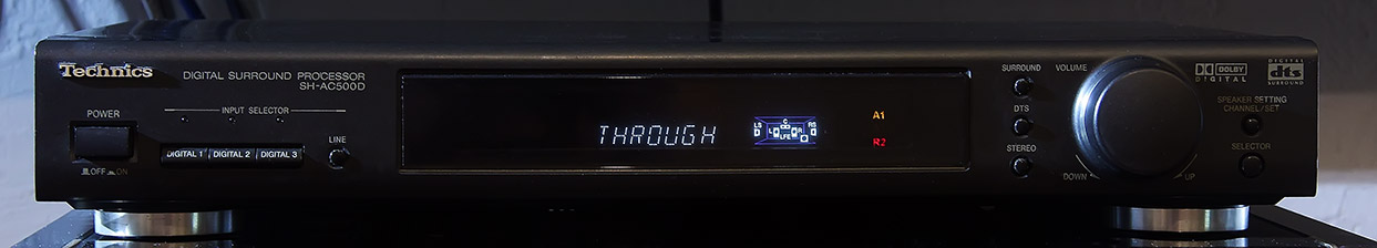
The picture above shows my version of SH-AC500D already modified. You can see input Amplifiers indicators on front display enabled. The yellow A1 stands for Amp 1 set for Front, the red R2 stands for Amp 2 set for Rear.
Additional front display DIRECT indicator is for total bypass of any hooked up in line devices and internal Digital Surround Processor of this unit from front signal path. This is mostly used for Audiophile quality Stereo playback. Direct connection of preamplifier with stereo power amplifier chosen from Yamaha MX-35X push button console, as shown on picture below.
How it works
The Input Selector Switch requires lot of additional inputs and output terminal jacks. The existing 5.1 Surround Inputs and Outputs have to be rerouted according to new system logic. The new Relay switching board and some logic control is required for it.
The original Digital Surround Processor in Technics SH-AC500D reminds fully functional and can be used in a system after choosing Digital Inputs buttons 1,2,3 on front panel of this unit. When the "Line" Input is set on the Front Analog signal is switched as primary signal path in the system. The Analog Front Signal named as "FA" (Front Analog) is dispatched through new Relay Board to Power Amplifiers A1, A2, A3, A4 accordantly to setting selected on Yamaha MX-35X Speaker Switch unit. The Rear, Center and Subwoofer I/O's are switched as well.
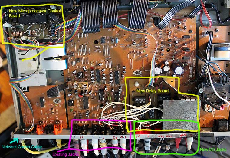
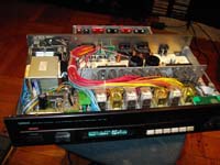
The picture above shows location of new Relay Board, new Input Output Jacks, Microprocessor Board and Network Communication Cable Jack.
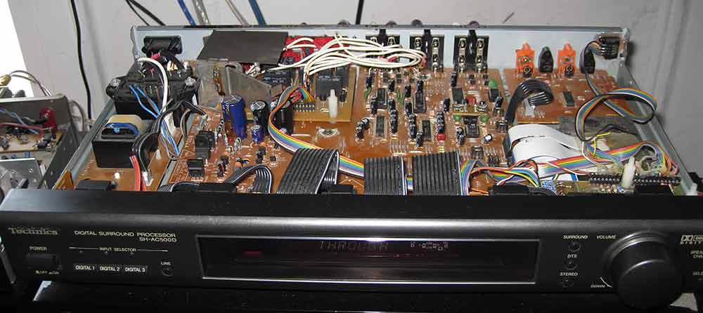
The picture below shows installation of new Relay Board and I/O Jacks in the case. Some extra holes in back wall has to be cut out and main board has to be cut out to make a space for new Relay board. Some traces must be rerouted on main board and main power transformer must be reversed and connected with wires to main board. The special metal screen was installed to protect analog signals on Relay Board from power transformer.

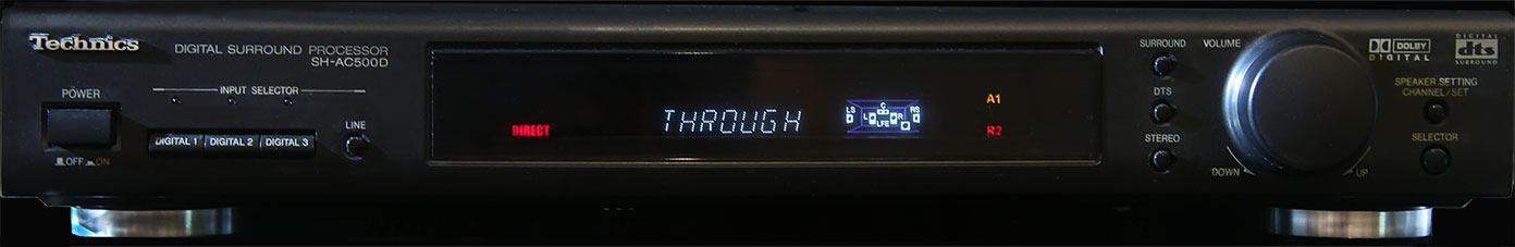
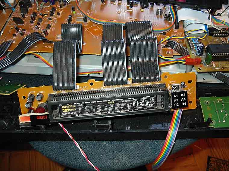
Next picture below shows front display modification. Status Indicators LEDs were added to display board. Four yellow LEDs with printed screens on top for A1,A2,A3,A4 front Amp connected status and red LEDs R2, R4 for rear Amp connected status. On left side "DIRECT" LED status light was installed. Status lights are controlled by microprocessor communicating with MX-35X unit through Network Cable.
The picture SCH. 3 shows partial schematics of input relay board. To avoid complication of logic of that schematics, only one channel for Front was shown. Also relays coils connections and transistor drivers were skipped.

SCH. 3
The picture SCH. 4 shows the brain of that input relay board. The microprocessor board is based on programmable microprocessor PIC 16F877 chip made by Microchip. The same like in Speaker Selector Switch MX-35X. In this application the chip in Technics SH-AC500DX is programmed as receiver (slave) of setting data from master chip from MX-35X. Any settings made on push buttons keypad on MX-35X are sent to the Input Selector AC500DX through proprietary network ITM NetCom1 cable connection.
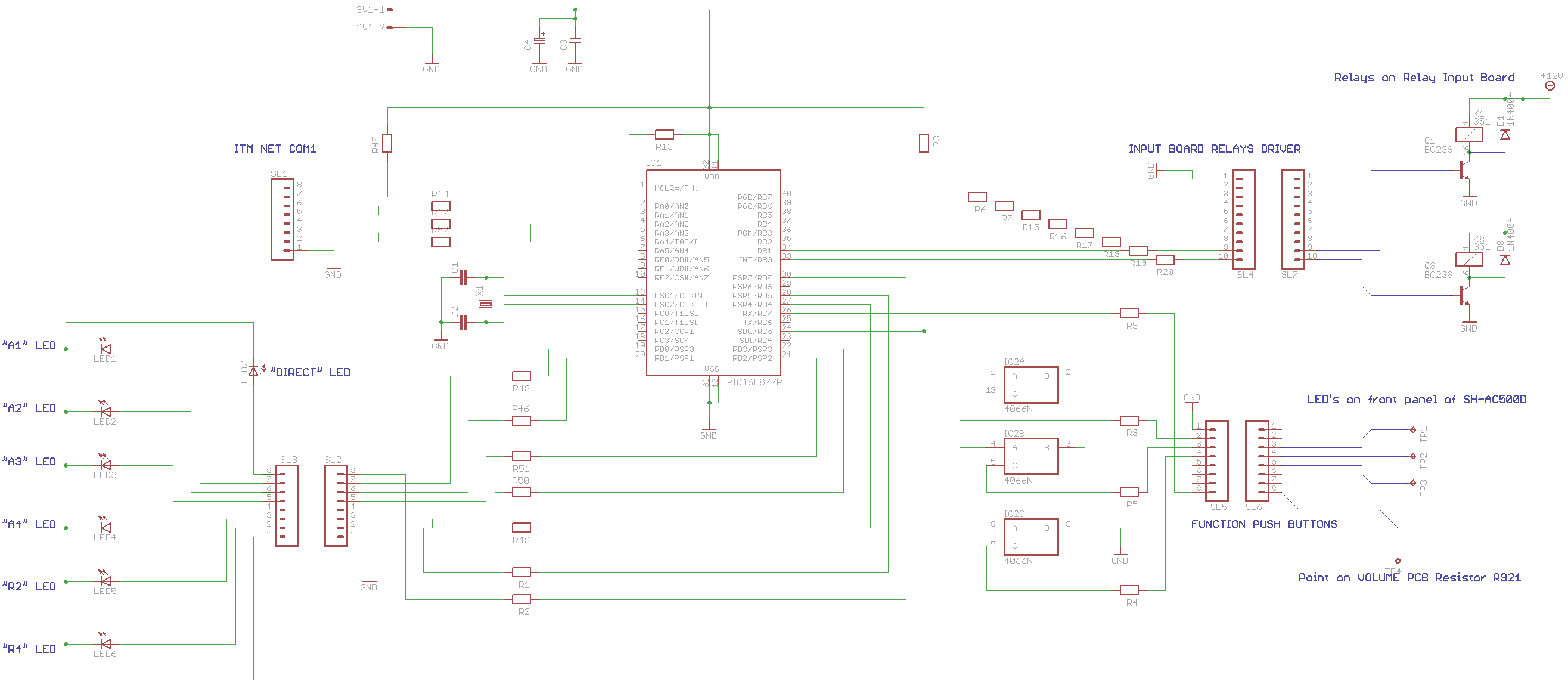
SCH. 4
The connector SL4 (Outputs RB0 -RB7) is to control transistor drivers for Input Relays. Outputs RD0-RD5, RD7 are for control LED's (A1,A2...R4, "DIRECT") front panel indicators. The connector SL5 is linking input RC5 using cascade switch made on CD4066 chip to detect setting on original Technics SH-AC500D subsystem. Any LED for DIGITAL INPUT 1,2,3 on Technics set to High state opens one of cascade 4066 switches, introducing High level to Input RC5 and that turns system to ANALOG "DIRECT" mode. Point Input RC7 is connected to resistor R921 on Technics volume switch board. Pressing any button on right, next to volume knob ("Stereo","DTS", "Surround", "Speakers Setting...","Selector") toggles "DIRECT" mode when LINE is selected. Points RA0,1,2 are for ITM Net Com1 network connection with Yamaha MX-35X unit.