
Microcontroller for Audio Multi brand System (Project Jupiter)
Navigation Bar (Click on It)
|
|---|
What if you have a bunch of Stereo Power Amplifiers and Surround System Speakers and you want to use all of them in different configurations without hassle to constant reconnect any wires and connectors?
You need Speakers Switch and some kind of Input Switch, switching Speakers sets and manual switch box and input preamp a same time is confusing and is a hassle.
Audiophiles usually have a lot power amps and they like quickly compare the sound quality and differences in sound or use them in ultra high end surround system, much better than any kind modern Digital Receiver (Amplituner).
That is why I created System controlling Speakers setting and Input setting the same time with microprocessor controller.
How it works?
Here is a video demo:
Speakers Switch Control
I had clear idea what to do, but how to put it together wasn't that clear. One solution was to manufacture my own case for this project. I could spend a fortune and I could got industrial looking metal box, looking like crap next to my Pioneer Elite Preamp and Players with grand piano finish.
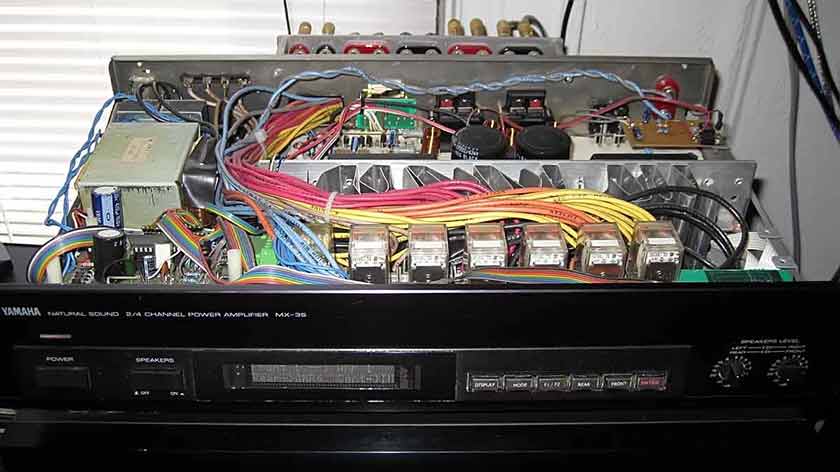
I decided to use the nice case of regular commercial Amp. These days you can buy great Amp from 80-ties or 90-ties on Ebay for little money and adopt the case for your needs. It has to be only in good cosmetic condition. The best suitable case for this project was Amp Yamaha MX-35.
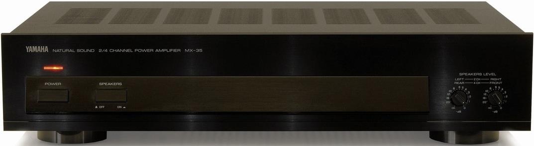
This little Amp has 4x 20W or 2x 40W power amplifiers good for Center Channel or additional surround channels and lot of room inside for some extra modifications.
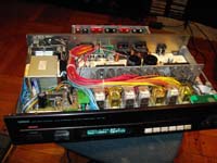
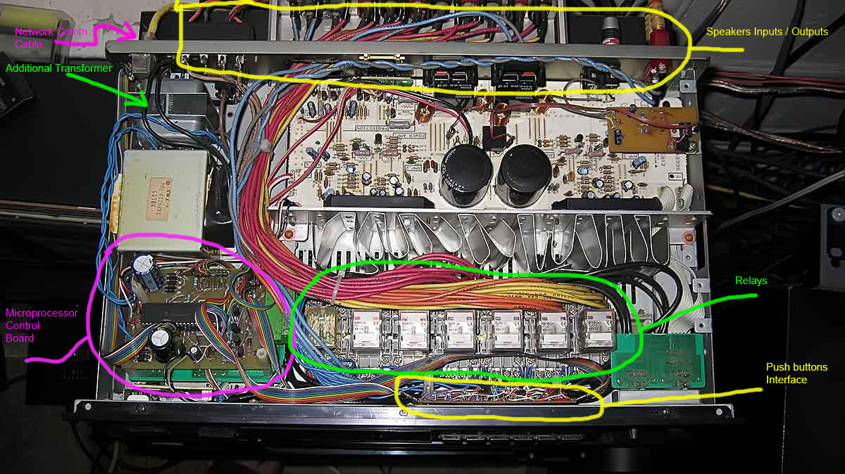
I had to fit in that case a lot of Relays, microprocessor control board and VFD Display with push buttons.
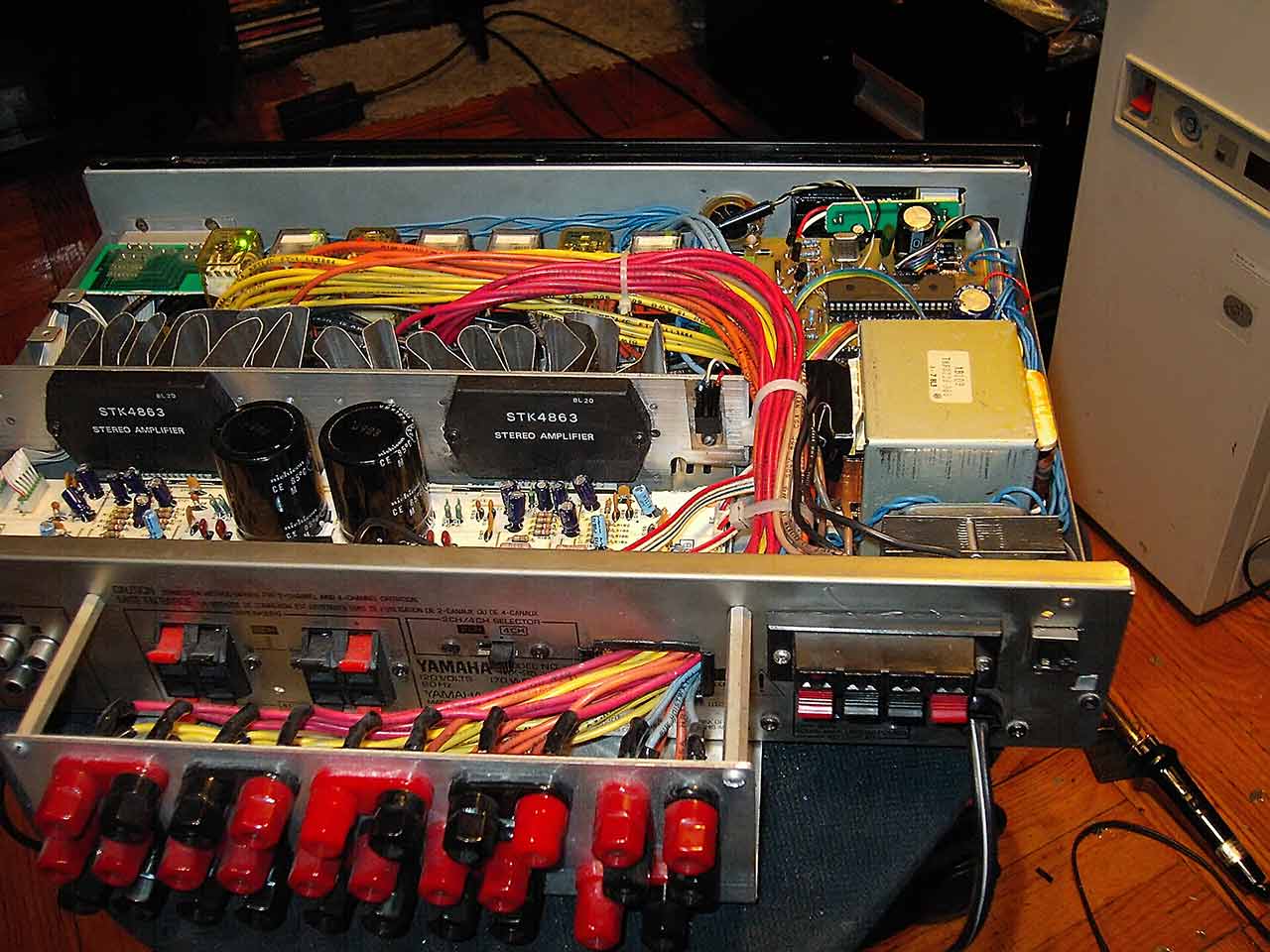
The final result Master Speaker Control Unit below.
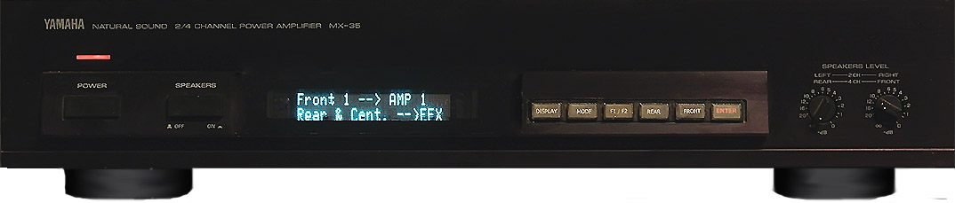
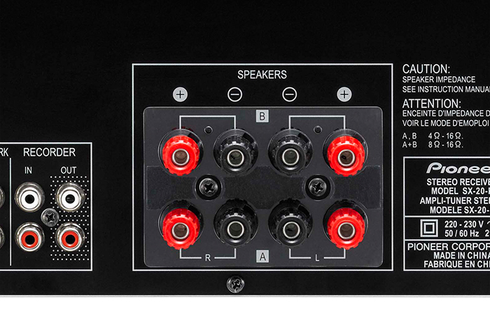
Front panel wall was redesigned by me by inserting VFD Display describing status of speakers connection. Also six function buttons were added to the panel. It improved appearance and functionality of this Amp greatly. Rear panel had to be redesigned totally. Now it has to contain input terminals for 4 stereo Amps plus Surround Amps for Rear Channels and Output terminals for 2 sets of Front Speakers and Surround Speakers with Center channel. Internal amplifier are used for Center Channel.
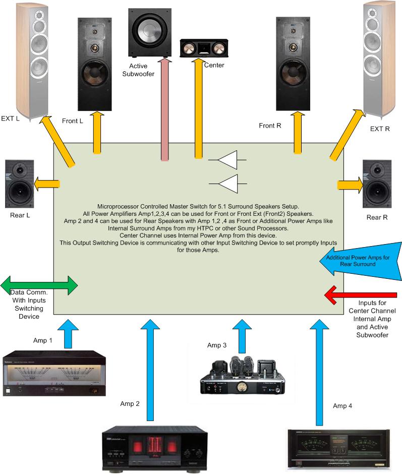
This unit is a major part of the system. It is a master control unit with push buttons to set required Speakers and Amps configuration. This works like regular Speaker Selector Switch allowing to connect chosen Speaker set to any of 4 Power Amplifiers quickly, without any hassle with switching wires manually every time when we want to compare Speaker Sets or Amplifiers.
Second part of that system, the automatic Input Selector for those Power Amplifiers is a separate unit and will be described later. This Input Selector is connected to the Speaker Switch and controlled via RJ45 network communication cable with proprietary protocol.
The Speaker Selector Switch inside modified Yamaha MX-35 Amplifier. (MX-35X)
How it works
All four Stereo Amplifiers are designated to play with selected Speaker sets Front 1 or Front 2 and Rear Surround Set by relays switches. We can chose which AMP is going to be main Front AMP and which is going to be Rear Surround. I can quickly compare various Power Amps, how they sounds, with only simple pushing the button on this unit.
The basic schematic below (SCH. 1) shows only one signal line for every Amplifier output and Speakers input for clear view. The Stereo Amplifier has usually four main speaker terminals marked L (Left)- RED and BLACK; R (Right) - RED and BLACK.
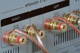
Back Panel with extra Speaker Terminals on my MX-35X during construction (pic. below)
The picture SCH.1 shows only one wire. The Relay Switch has to switch all 4 wires at the same time from every Amp, that is why, we have to use 4P/2T Relays with contacts rated for 5-10A AC. Four Pole relays must be used, because those lines have to be separated totally from each other, any of lines cannot be crossed. Even the Black terminal (usually Neutral) cannot be connected with other Power Amplifier. It can cause interference or even serious damage of all Power Amplifiers. Keep all separate.
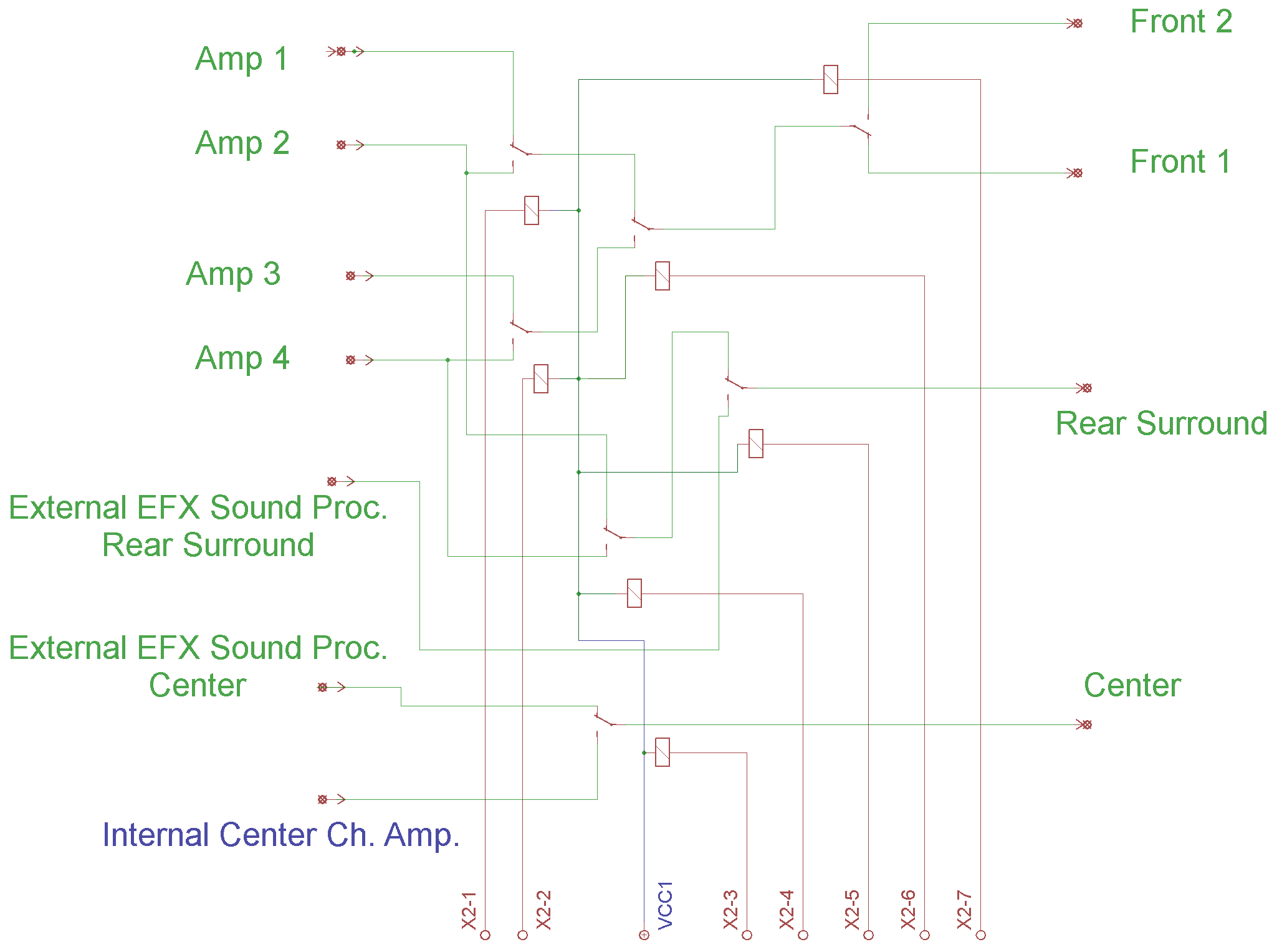
SCH.1
The brain of the system is made on Microprocessor. I used the microprocessor made by Microchip. This system was design in 2003 and the one of the most popular microprocessor at that time was PIC16F877 . It is very popular versatile and powerful programmable microprocessor easy to program with lot of inputs/outputs. The picture SCH. 2 below shows PIC16F877 chip with ports RD0 to RD6 hooked to transistor drivers Q1 to Q7 controlling Relays X2-1 to X2-7.
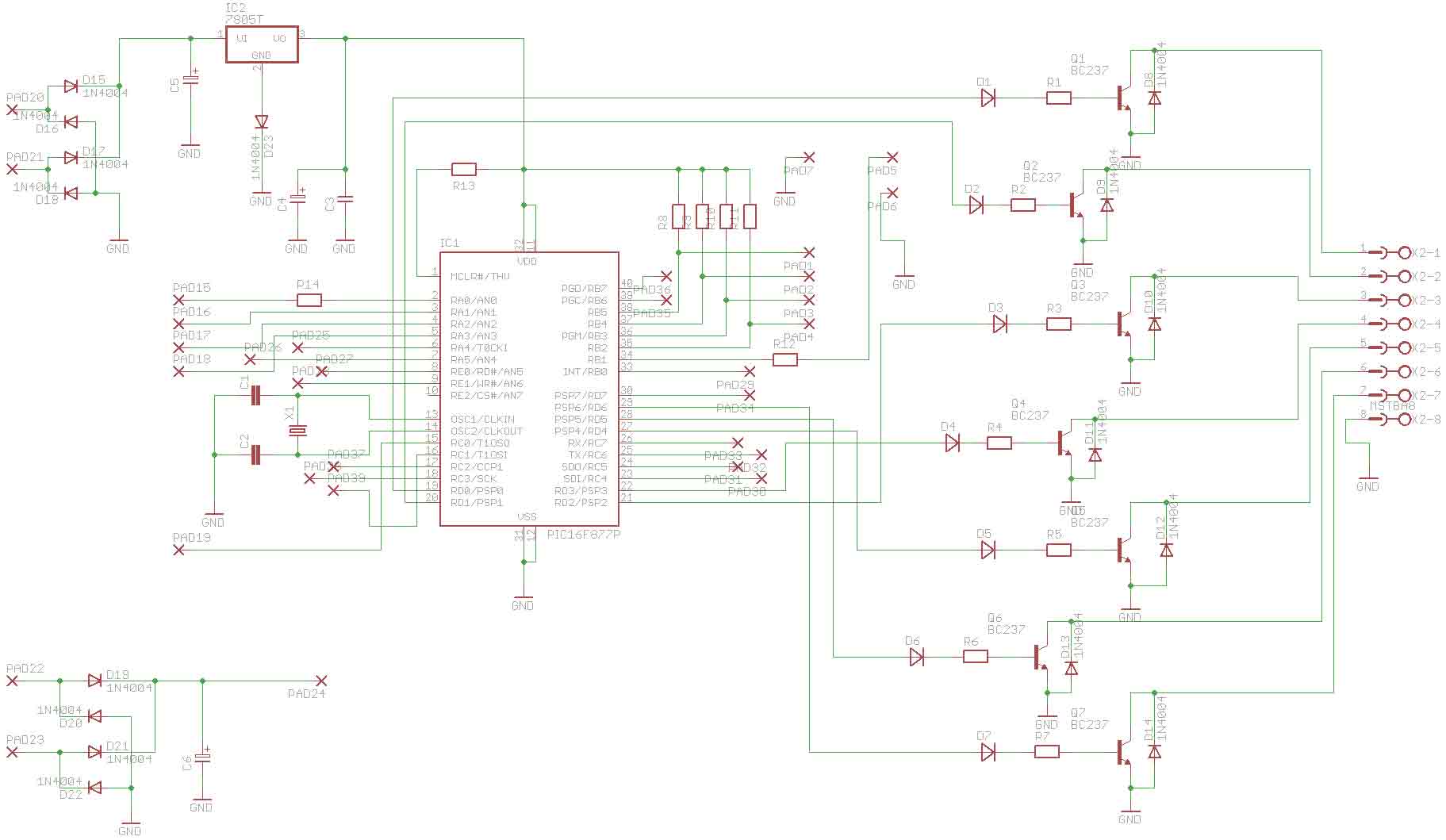
SCH. 2
The port RC7 is for Noritake serial VFD Display. The port RC1 for speaker. Ports RB0 to RB5 are used for push buttons control. Ports RA1, RA2, RC5, RC6 are for proprietary serial connection with Inputs Control Device.
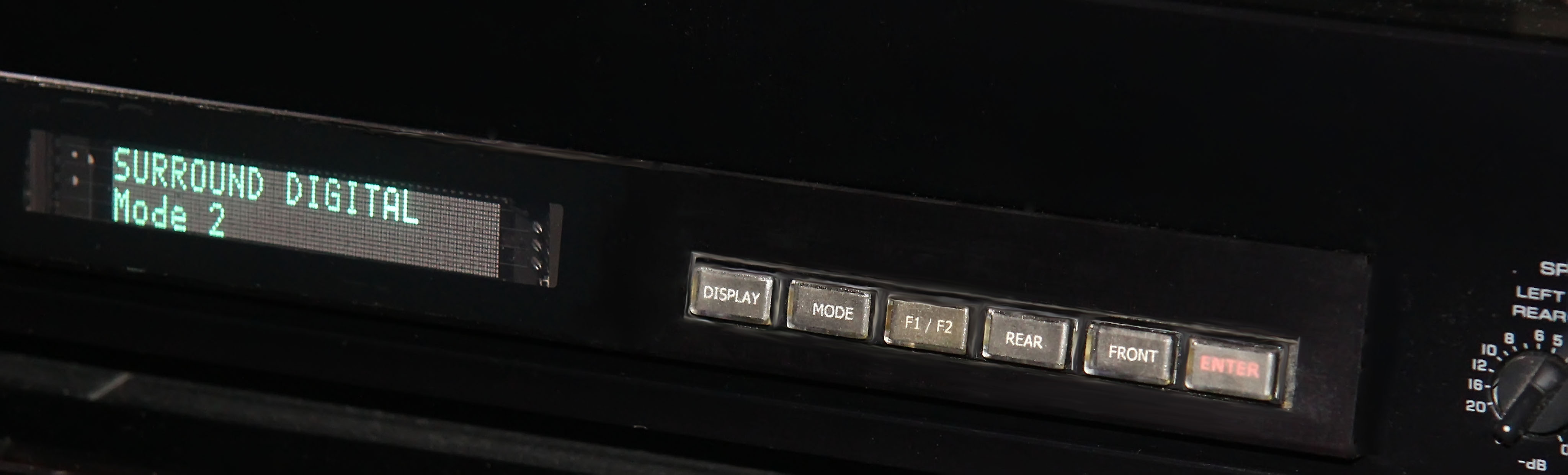
Push buttons on front panel of this unit are used to set required system speakers and amplifiers configuration.
The MODE button sets 3 basic master configurations:
1. ANALOG - Front Speakers (1) connected to Amp1 ; Center and Rear Surround Speakers connected to External EFX Amps.
2. DIGITAL - Front Speakers (1) connected to AMP1 ; Rear Surround Speakers connected to AMP2 ; Center Speaker to Internal Yamaha MX-35X Amp.
3. DIGITAL MODE 2 - Front Speakers (1) connected to AMP2 ; Rear Surround Speakers connected to AMP4 ; Center Speaker connected to Internal Amp.
The F1/F2 button sets Speakers Front 1 or Front 2. It allows quick compare 2 sets of stereo front speakers or reroute audio program to speakers located in different room, etc.
The button REAR sets Rear Surround Speakers in 3 basic configurations independent from master MODE settings.
1. REAR Speakers connected to EFX Amp such Surround Amps from my HTPC or other Sound processor with power Amps.
2. REAR Speakers connected to AMP2
3. REAR Speakers connected to AMP4
The FRONT button allows to choose Main Front AMP independent from master MODE setting.
The Front Amp can be set as AMP1, AMP2, AMP3 or AMP4.
The AMP1 and AMP3 are used as primary stereo Amplifiers, so they cannot be used as REAR AMPs in this system to minimize unnecessary system complication. The AMP3 is my Vacuum Tube Amplifier VT-1SE and when it plays proper stereo material I don't need any multichannel distraction.
The DISPLAY button is for switching off/on the VFD display.
TOP of Page